M2DO

Our Research


Topology Optimization for Fluid-Structure Interaction

Computational fluid structure interactions (FSI) pose significant numerical challenges due to the inherently non-linear and time-dependent nature of coupled multiphysics. An additional difficulty is the discretization of the fluid-structure interface to accurately capture the complicated dynamic motion and deformation of the fluid-structure interface and to impose coupling conditions. The complexity further increases when considering topology optimization of such FSI problems, since the interface not only deforms under the action of the fluid, but its shape also changes throughout the optimization procedure.

1. Modified Immersed Finite Element Method

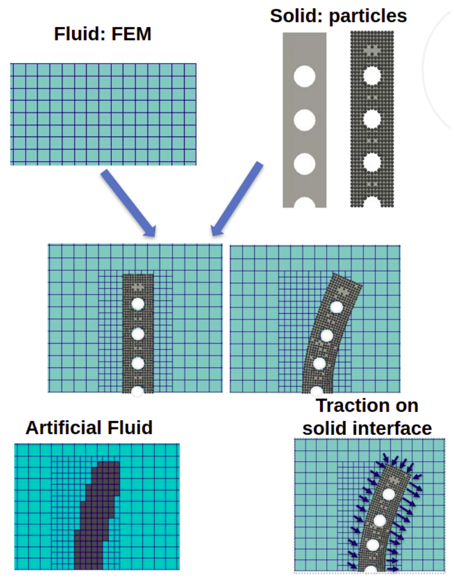
To address the main challenges associated with topology optimization of FSI problems, the level set topology optimization is combined with the modified immersed finite element method (mIFEM) developed by Wang and Zhang (2013). The mIFEMthat leads to a formulation with separate solid and fluid domains. The fluid can see the solid through an artificial fluid region overlapping with the solid whereas the solid sees the fluid as a traction on the FSI interface. A useful feature of this formulation is that no assumption is made on the discretization methods used to solve the governing equations of each domain. Here, for the Eulerian fluid domain the finite element method (FEM) is used whereas the Lagrangian solid domain is analyzed using the reproducing kernel particle method (RKPM).

Fig. 1: Combination of mIFEM, LSTO and RKPM. The solid, geometrically defined by LSTO and analyzed with RKPM floats on top of the Eulerian fluid FEM grid. The two see each other through the artificial fluid region on the fluid and the fluid traction on the solid boundary.

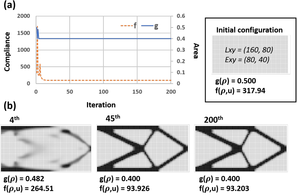
2. Compliance Minimization Under FSI

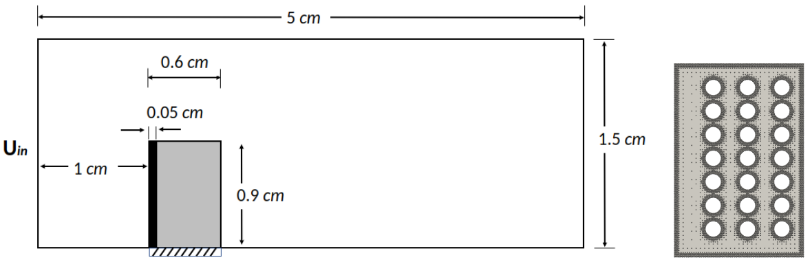
Most topology optimization works on FSI consider the leaflet example which is shown in Fig. 2. The setup consists of a rectangular beam with fixed support on the bottom which is placed inside a fluid field.

Figure 2: Leaflet example setup (left) and Initial design (right)

The optimized designs for two Reyonlds numbers, 0.01 and 100, are shown in Fig.3. It can be observed that the two solutions have several differences, especially on the FSI interface. The boundary is more rounded for the low Re but it becomes more flat, nearly bended inwards, for the high Re.

(a)

(b)

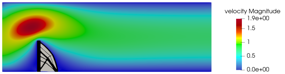
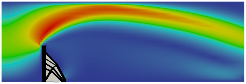
Figure 3: Final leaflet design and velocity profile for: (a) Re = 0.01 and (b) Re = 100.

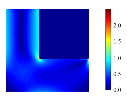
Upon examining the pressure fields in for the two cases in Fig. 4, it can be seen that pressure around the FSI interface is positive for the low Re acting inwards towards the structure. Spherical shapes are ideal for such hydrostatic loads which may explain the tendency of the boundary to become more rounded. On the other hand, the pressure at the FSI interface is negative for the high Re case, which may cause the boundary to go in the opposite direction.

(a)

(b)

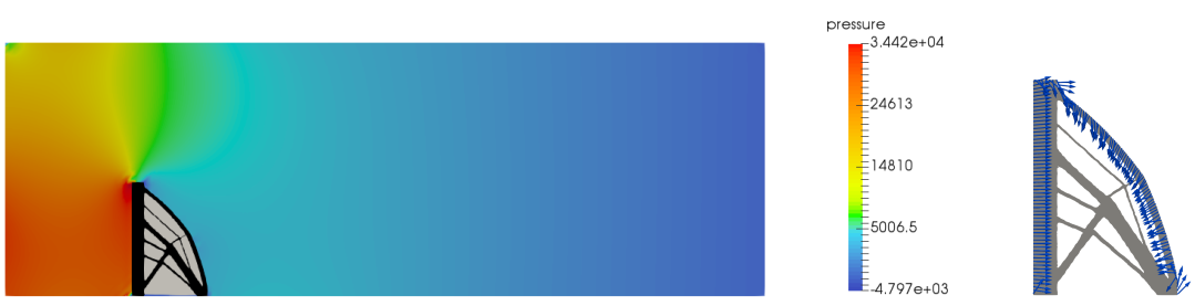
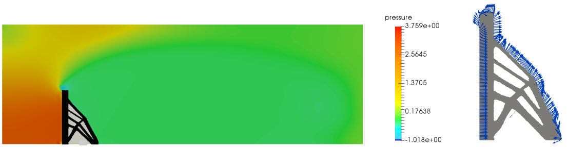
Figure 4: Final leaflet design, pressure profile for: (a) Re = 0.01 and (b) Re = 100. The arrows in the figures on the right illustrate the direction of the pressure load.

Relevant publications:

  1. Neofytou A., Yu F., Zhang L. T. and Kim H. A.(2022) "Level Set Topology Optimization for Fluid-Structure Interactions", AIAA Aviaiton Forum, CA, USA, January.
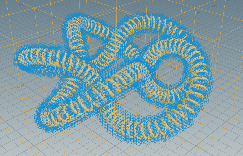
Multiscale and Multiphysics Design Optimization Considering Manufacturability

With the development of Additive Manufacturing (AM) technology, architected materials are attracting increased attention owing to their ability to manipulate material behavior. Through AM technology, many unconventional multiscale and multiphysical effects can be realized. Topology optimization (TO) presents a systematic mathematical approach to the design of optimal materials and structures.

Fig. 1: Simultaneous structural and material design approach [1]

To further extend the design space, we developed a simultaneous material and structural optimization approach, in which the macroscale design domain can be divided by any number of subregions as the practical requirements or the designer's insight, and the microstructures are assumed to be periodic in each subregion (Fig. 1). In this sense, both the macroscale structure and all the unit cells can be designed to improve the structural performance. In addition, by linearization technique, both the macroscale structure and unit cells can be optimized in parallel to save considerable computational efforts in our level set topology optimization framework [2].

Nevertheless, homogenization-based TO has a salient limitation as it does not consider how the unit cells are interconnected within the material. Since the unit cells are often disconnected within the structure (Fig. 2), the architecture of the material becomes implausible in reality. To overcome such issue, we introduced a connectivity index approach to optimally design the multiscale structures with multiple well-connected microstructures (Fig. 3) [3]. Currently, this approach is adopted to study coupled multiphysics design problems where the structure interacts with its surroundings, e.g., mechanical-thermal systems, through which the quantitative benefit and potential introduced by multi-scale architecture can be understood clearly.

Fig. 2: Multiscale optimized design of the L beam example with connectivity issue of microstructures (a) macroscale structure and (b) microstructures

Fig. 3: Optimized L beam design through connectivity index approach (a) macrostructure and (b) microstructures [3]

Relevant publications:

  1. Sivapuram R, Dunning PD, Kim HA (2016) Simultaneous material and structural optimization by multiscale topology optimization, Structural and multidisciplinary optimization, 54(5), 1267-1281, DOI 10.1007/s00158-016-1519-x.
  2. Dunning PD, Kim HA (2015) Introducing the sequential linear programming level-set method for topology optimization, Structural and Multidisciplinary Optimization, 51(3), 631-643, DOI 10.1007/s00158-014-1174-z.
  3. Du Z, Zhou XY, Picelli R, Kim HA (2018) Connecting microstructures for multiscale topology optimization with connectivity index constraints, Journal of Mechanical Design Special Issue, submitted.

Large-Scale Topology Optimization

In large-scale level set topology optimization, the operations involved in morphing the geometry are slow. Moreover, simulating the physical characteristics, such as stress and stiffness is computationally expensive. This prohibitively expensive computational issues are addressed using a VDB, a tree data structure to represent the geometry. Moreover, we also implement the finite element analysis using parallel computing software PETSc, which significantly speeds up the topology optimization process.

1. VDB Data Structure

VDB is a sparse and hierarchical tree data structure (like octrees) that efficiently represents geometries, resulting in fast convergence characteristics. In the first example, we show a geomertrical optimization of a helix-torus structure obtained using a grid resolution of 2000 x 800 x 2000 = 3.2 billion voxels.

(a) Optimization evolution

(b) Close-up view of VDB data structure

Fig. 1: Geometrical optimization of a helix-torus structure.

2. Finite Element Analysis using PETSc

The torsion ball problem is to design a lightweight structure which is stiff under a torsion load. The structure is clamped under torsion load. The stiffness of the ball is characterized using 6 million finite elements. The compliance of the structure is minimized for a volume constraint of 3%, and the optimization converges in 3 hours.

(a) Optimization evolution

(b) Topology shown on the hierarchical VDB grid

Fig. 2: Optimized lightweight torsion ball that is stiff under torsion.

The torsion ball problem obtained using a higher resolution mesh (20 million elements) is shown below for a volume constraint of 1%.

Fig. 3: Tosion ball obtained using 20 million elements.

Fig. 4: 3D printed torsion ball.

The third problem is to design a lightweight bridge structure that is stiff under a pressure load on top with its corners pinned. Due to symmetry, only one half of the domain is modelled. In Figure 5a, the evolution of the bridge obtained using 1 milion elements is shown. In Figure 5b, the optimum bridge topology obtained using 33 million elements is shown.

(a) Optimization evolution using 1 million elements

(b) Topology of the bridge obtained using 33 million elements (100 million DOFs).

(c) Topology shown on the hierarchical VDB grid.

(d) 3D printed bridge.

Fig. 5: Optimized lightweight bridge that is stiff under compression.

Relevant publications:

  1. Kambampati, S., Jauregui, C., Museth, K., & Kim, H. A. (2018) "Fast level set topology optimization using a hierarchical data structure", AIAA Aviaiton Forum, GA, USA, June.
  2. Kambampati, S., Jauregui, C., Museth, K., & Kim, H. A. (2018) "Fast structural level set topology optimization by means of a hierarchical data structure", WCCM, NY, USA, July.

Stress-Constrained Topology Optimization

Stress optimization is one of the key factors for structural design in a wide range of engineering problems. Designs such as the one from Fig. 2 present stress concentrations that might lead to structural failure in practice.

(a) Design domain

(b) Von Mises stress field

Fig. 2: Benchmark L-bracket example.

It is acknowledged that considering stress within a topology optimization framework is hard and partially unresolved. Notably, Le et al. (2010) presented a practical solution for stress-constrained design in the context of density-based topology optimization. However, stress constraints are still hard to achieve with other methods, such as level sets. Our level set method has been capable to address stress-based shape and topology optimization.

Fig. 3: Stress-based optimal designs for the L-bracket.

Our approach uses a handful of numerical ingredients to deal with the challenges of stress-based design, namely, singularity problem, the local nature of the stress and the highly nonlinear stress behavior. The application of a p-norm aggregation function and other techniques allows the method to address stress-constraints and multiple load and stress cases.

Fig. 4: Multiple load and stress cases.

Fig. 5: 3D printed stress-based L-bracket.

Future work will consider the application of our stress-based level set method to different problems, e.g., microstructural stresses, stress control, etc. We gratefully acknowledge Prof. Julian Norato, from the University of Connecticut, for the collaboration in this work; and, also, the Engineering and Physical Sciences Research Council (EPSRC) from the United Kingdom for the financial support in this research.

Relevant publications:

  1. Picelli R, Townsend S, Brampton C, Norato J, Kim HA (2017) "Stress-based shape and topology optimization with the level set method", Computer Methods in Applied Mechanics and Engineering, accepted.
  2. Picelli R, Townsend S, Brampton C, Norato J, Kim HA (2017) "Stress minimization using the level set topology optimization", AIAA SciTech Conference, Grapevine, TX, USA, Jan.
  3. Brampton C, Dunning PD, Kim HA (2015) "Stress-constrained optimisation using SLP level set topology optimisation method", AIAA SciTech Conference, Kissimmee, FL, USA, Jan.

Heat Transfer Optimization

The level set method topology optimization for 2D and 3D convective heat transfer problems is presented here.

1. Heat Dissipation Problem

First of all, we show the the optimized heat dissipation structure which is a lightweight design that dissipates heat being produced everywhere.The evolution of the topoology is shown in Fig. 1a obtained using 1 million elements. The optimized structure shown in Fig. 1b is obtained using 32 million elements, showing branches emanating from the heat sink and drawing heat from everywhere in the designdomain.

(a) Optimization process

(b) Topology obtained using 32 million elements

Fig. 1: Optimized lightweight heat dissipating structure.

2. Heat Flow Problem

Stokes flow and Darcy potential flow, which are linear flow models, are used to simulate the flow using the finite element method. The resulting velocity field is used in a convection-diffusion model to simulate the heat transfer using the finite element method. A linear combination of the pressure drop and the average temperature is considered as the objective function, which is minimized subject to a volume constraint. The optimized topologies obtained for different problem cases for Stokes flow and Darcy potential flow are presented.

The schematic of second problem domain is shown in Fig. 2. The boundary conditions of the flow entering through the centerline on left side at V=0.2 m/s and exiting through the centerline on the right hand side is shown in Fig. 2. The domain is subject constant heating of Q=200 kW/m^3. The boundary conditions are T=0 at the fluid entry region and P=0 at the fluid exit region. The FE mesh is discretized into 160\times160 elements. Due to symmetry, only the top half of FE domain is modeled. The objective is to minimize k\times average temperature+(1-k)\times pressure drop subject to a volume constraint of 50%.

Fig. 2. Design domain of flow problem.

The topologies obtained for Darcy flow for different values of k are shown in Fig. 3. It can be seen that the number of channels increase as k increases.

Fig. 3. Darcy flow results.

The velocity and temperature distribution is shown in Fig. 4. For k = 0.4, most of the flow goes through the center and results in high temperatures. For k = 0.7, the flow is distributed more uniformly, resulting in lower temperatures.

Fig. 4. Velocity and temperature distributions of Darcy flow results.

The topologies obtained for Stokes flow for different values of k are shown in Fig. 5. For lower values of k, the width of the channels going through the center is high. On the other hand, for higher values of k, the width of the channels going around the center are high.

Fig. 5. Stokes flow results.

Similar to the Darcy flow case, the velocity and temperature distribution is shown in Fig. 6. For k = 0.4, most of the flow goes through the center and results in high temperatures. For k = 0.7, the flow is distributed more uniformly, resulting in lower temperatures.

Fig. 6. Velocity and temperature distributions of Stokes flow results.

Now we are trying to solve 3D problem. The schematic of 3D problem domain is shown in Fig. 7, which is under constant heating of Q=20 kW/m^3 , with flow entering the domain through the center line on the left side with V=0.2 m/s, and exiting through the center on the right side is shown in Fig. 7. The FE mesh is discretized into 80\times80\times80 = 0.52 million elements. Due to symmetry, only a quarter of FE domain is modeled. The objective is to minimize k\times average temperature+(1-k)\times pressure drop subject to a volume constraint of 15%.

Fig. 7. 3D design domain.

The optimized topology obtained using Darcy potential flow is shown in Fig. 8 with k = 0.7 and k = 0.4.

Fig. 8. Darcy flow results.

The optimized topology obtained using Stokes flow is shown in Fig. 9 with k = 0.7 and k = 0.4.

Fig. 9. Stokes flow results.

Aeroelastic Topology Optimization

A coupling between unsteady aerodynamics and structural vibration gives rise to the flutter phenomenon: steady or growing oscillations which can lead to catastrophic structural failure.

(a) Aeroelastic damping curves for a scale NASA CRM wing

(b) Aeroelastic mode shape at the flutter point (zero damping)

Fig. 5: Aeroelastic stability information is contained in the vibrational damping parameters: Negative damping implies stability and vice-versa. We calculate structural and aerodynamic behaviour via the finite element and doublet-lattice methods, linking them via surface splines.

While aircraft optimization, with an emphasis on avoiding aeroelastic instability, has been studied since the 1960's, few have utilised a topology optimization approach. We are employing the level set method to represent and optimize components of wings, such as the skin thickness distribution.

(a) Example level set field

(b) Resulting skin thickness distribution

Fig. 6: Wing structures are represented by the level set method:
Skin thickness is defined at the finite element nodes, and is mapped via the level set function such that binary topologies are obtained.

Wing weight is typically the measure to be optimized, with constraints placed on the eigenvalues of the flutter equation; such ensures stability under the flight conditions of interest. The level set optimization results in aeroelastically-tailored structures, which leverage the known aeroelastic phenomena such as mass-balancing and bend-twist coupling. Our approach has proven capable of significantly reducing weight while maintaining flutter and divergence speed.

(a) NASA CRM wing planform

(b) Delta wing planform

Fig. 7: Optimal wing structures produced by the level set method. For each, the flutter speed is equal to or great than the reference design.

Future works will include extension to three-dimensional wing structures, and inclusion of the aerodynamic planform into the optimization process. We gratefully acknowledge the support of the European Office of Aerospace Research and Development, Air Force Office of Scientific Research, and NASA Langley for this research.

Relevant publications:

  1. Townsend S, Stanford B, Picelli R, Kim HA (2017) "Structural optimization of plate-like aircraft wings under flutter and divergence constraints", AIAA Journal, submitted.
  2. Dunning P, Stanford B, Kim HA (2015) "Coupled aerostructural topology optimization using a level set method for 3D aircraft wings", Structural and Multidisciplinary Optimization, 51(5), 1111-1132, DOI: 10.1007/s00158-014-1200-1.
  3. Dunning P, Stanford B, Kim HA (2015) "Level-set topology optimisation with aeroelastic constraints", AIAA SciTech Conference, Kissimmee, FL, USA, Jan.
  4. Dunning P, Stanford B, Kim HA, Jutte C (2014) "Aeroelastic tailoring of a plate wing with functionally graded materials", Journal of Fluids and Structures, 51, 292-312, DOI: 10.1016/j.jfluidstructs.2014.09.008.

Topology Optimization with MDAO

Topology optimization, which determines the optimum shape and layout for given objective function and constraints, is considered to be capable of giving out optimum configuration out of large design spaces and hence has a high potential when it is combined with different regimes of physics (multiphysics) and scales (multiscale). In the application context, however, the potential is not fully exploited partially due to the challenges come out of non-technical barriers. First, there is a limited number of systematic object-oriented approaches that reduce the recurring tasks of coding. It is a limiting factor considering the wide background of the researchers who are interested in the structural optimization. Moreover, the numerical treatments are also in need in addition to the building blocks of the topology optimization, say getting consistent sensitivities, by which the overall implementation involves manual, repetitive tasks which are prone to user-induced errors. In this respect, the robust framework on which topology optimization is running is highly required.

In this regard, topology optimization implementations stand to benefit from changes that result in more code modularity, ease of restructuring, and more automated derivative calculations. We propose using OpenMDAO, a computational framework for multidisciplinary design optimization (MDO) created and maintained by NASA Glenn. It is a generic platform upon which gradient-based optimization algorithms and the relevant tools are implemented with the aforementioned improvements, which are reformatted in topology optimization context in the present work.

In OpenMDAO models are built hierarchically by pre-defined classes which are encapsulated to provide non-intrusive inspection of inputs, output, and partial derivatives. Such modularity leads to both restructurability and reusability. Once the object is programmed, further modifications are is unnecessary as long as the governing equations remain intact (reusability). Also, these modules are freely arranged and therefore reformatting of the information requires only changes in connectivity (i.e., a coupling between the modules); the required changes to the global derivative are applied automatically (easy restructurability). These two traits are beneficial as these significantly reduce repetitive programming and user-induced error.

1. Topology Optimization Methods

Two widely used topology optimization techniques---density-based and level-set---are implemented to serve as reference code designs. Even though the basis of the language is written in the context of MDO, commonalities found within general optimization enables such integration. Design structure diagrams, which are created automatically through OpenMDAO Visualizer, visualize the flow of the data and decomposition of the techniques.

Fig. 1. (Left) Design structure of SIMP method; (Right) (a) Convergence curve (b) the material configuration, area fraction (g) and compliance (f) at the given iterations.

Fig. 2. (Left) Design structure of the level-set topology optimization method; (Right) (a) Convergence curve (b) the material configuration, area fraction (g) and compliance (f) at the given iterations.

2. Demonstration of Flexible Configuration

To demonstrate the flexibility of the new topology optimization architecture, two variations on the density-based topology optimization approach are shown.

2.1. Parameterized level-set topology optimization

The reusability of the modules is exemplified by extending the present objects to a new topology optimization formulation that bears similarities to the parameterized level-set topology optimization approach.

Fig. 3. (Left) Design structure matrix of the parametric level-set approach for topology optimization; (right) (a) Convergence curve (b) the material configuration, area fraction (g) and compliance (f) at the given iterations.

2.2. Flexible arrangement of the module

The restructurability of the program is also demonstrated by rearranging the order of the density filter (DensityFilterComp) with respect to other objects. Thanks to the modular architecture of OpenMDAO, minimal changes are required in rewiring the connectivity between pre-built objects. This is in contrasts to the topology optimization programs such as the minimalistic educational implementations. No matter how simple the program might be, it is still true that small tweaks such as the removal of the filter require re-programming of the code; not only the functions but also the sensitivities must be changed accordingly.

Fig. 4. A demonstration of restructurability. (a) the design structure matrix of the SIMP method, where the filter object is rearranged with respect to that of the penalization step, and (b) a code snippet for the reconfiguration that exemplifies the easy reconfiguration; commented commands are marked by blue and corresponding changes are marked by red.

The completed work is published, and the codes of the present work are open to public access (https://github.com/chungh6y/openmdao_TopOpt). Instruction for installation and running the program can be found therein. We gratefully acknowledge NASA Glenn for the collaboration in this work.

Relevant publications:

  1. Chung H., Hwang J., Gray J., Kim HA (2017) "Implementation of topology optimization using openMDAO", AIAA SciTech Conference, Kissimmee, FL, USA, Jan.
  2. Chung H., Hwang J., Gray J., Kim HA (2019) "Topology optimization in OpenMDAO", Structural and Multidisciplinary Optimization, published online.
  3. Gray. J., Hwang J., Martins J.R.R.A., Moore. K.T., Naylor B (2019) “OpenMDAO: An Open Source Framework for Multidisciplinary Analysis and Optimization”, Structural and Multidisciplinary Optimization, published online.

Nonlinear Thermoelastic Topology Optimization

Thermoelasticity is a type of elastic behavior where temperature change is coupled with stress state within the structure. The phenomenon is widely considered in aerospace engineering, where the temperature change is always involved during its operation and fabrication. Often, these thermally induced behaviors have an adverse effect on the structure, for example, an unintended warping. To design that alleviates such a negative effect, topology optimization considering thermoelasticity has been widely investigated and proven to design structures that are optimal when mechanical and thermal loads are imposed simultaneously. However, there are only a few works of literature that considering a nonlinear thermoelastic case, which refers to the case where either mechanical or thermal loads induce a large deformation of the structure.

In this research, we propose level-set based topology optimization of thermoelastic nonlinear structure, which is essential when structure experiences a large deformation.

Fig. 1. Benchmark bi-clamped beam. Mechanical point load \bm{f}^m and thermal expansion \alpha\Delta T are simultaneously imposed.

1. Mechanical Nonlinearity

Contrary to the linear case, the optimal design layouts change with respect to the sign and magnitude of \bm{f}^m when structural nonlinearity is considered during the optimization. Figure 2 demonstrates such material layouts, for prescribed mechanical loads only.

Fig. 2. Optimized material layouts for prescribed mechanical loads \bm{f}^m.

Fig. 3. Comparison of load-carrying capacity between design layouts obtained by the topology optimization considering linear (dotted line) and the nonlinear (solid) structural analysis.

For a range of \bm{f}^m\in[-0.01,0.01] deformation of the nonlinear optimum structures gradually changes in proportion with the mechanical loading. A large deformation is found to be salient when ||{f}^m||=0.005 since the maximum displacement is in the order of height of the structure. In the linear case, however, tip displacements are computed only for a load range of \bm{f}^m\in[-0.01,0.0016], and shows a displacement of substantially higher magnitude throughout the range: when the load is higher than 0.0016, a structural equilibrium is not attainable for a standard Newton-Raphson method. It is therefore concluded that the linear design has much less structural load capacity due to the presence of slender, compressed members populated in the layout.

2. Thermoelastic Design

We extend the previous discussion on the nonlinear elastic design to nonlinear thermoelasticity. The effect of uniform temperature change \Delta T is examined herein, by fixing the mechanical load \bm{f}^m={10}^3 while gradually increasing \alpha \Delta T within the range of [-{10}^{-2},+{10}^{2}]. Such a range roughly coincides with the amount of thermal expansion found in high-temperature operation conditions.

Fig. 4. Optimized layouts considering thermoelastic loads, obtained each by employing linear and nonlinear thermoelastic analysis.

For each layout, thermoelastic load that corresponds to one assumed during the optimization is employed for the analysis. The resulting displacements are shown in Fig. 5. Deflection of the linear thermoelastic optimums is plotted against changing \alpha \Delta T and marked by dotted lines and compared with that obtained for the nonlinear design optima. Since the mechanical nonlinearity is not significant in the assumed load case {f}^m=10^{-3}, the displacements of the linear and nonlinear coincides near \alpha \Delta T=0. As one may expect, the deflections of the design layouts concerning linear thermoelasticity envelopes these of the nonlinear elasticity, which denotes the relative optimality of the designs of nonlinear layouts. However, as shown in \alpha \Delta T \in [0.004, 0.01] where V-shape layouts are optimum solutions in the linear optimization, a strong deviation between the linear and nonlinear results are shown. The V-shape structure buckles therein, which is inevitable when only the linear thermoelasticity is considered as such structural instability is not taken into account in the linear optimization. As a result, it is concluded that even in the case where both the mechanical and thermal loads are small, often nonlinear thermoelasticity are necessarily considered. This finding again emphasizes the needs of nonlinear consideration in thermoelastic structure design.

Fig. 5. Comparison of the optimal compliances with respect to changing \alpha \Delta T.

Through the investigation, the incorporation of the nonlinearity is found to be significant in both mechanically-driven and thermally-driven nonlinear regimes, again demonstrate the importance of incorporating the nonlinearity to the thermoelastic design.

The authors acknowledge the support from DARPA (Award number HR0011-16-2-0032). H. Alicia Kim also acknowledges the support of the Engineering and Physical Sciences Research Council (grant number EP/M002322/2).